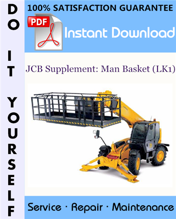
This is the COMPLETE factory Supplement Serivce Manual for the JCB Loadall. The information covers JCB Loadall machines fitted with the LK1 Personnel Platform.
Machine Model and Serial Number:
This manual supplement provides information for the LK1 Work Platform, compatible with the following models in the JCB machine range:
3-Stage Boom Machines
– 532-120
– 535-125
– 535-140
– 537-135 (550)
– 540-140 (550-140)
4-Stage Boom Machines
– 540-170 (550-170, 5508)
This Manual Covers:
=========
Introduction
General Information
Machine Model and Serial Number
About this Supplement
Safety Check List
System Overview
Introduction
Controls
Remote Servo Control
Emergency Operation
Motion Cut Out (MC) (if fitted)
Component Location and Identification
System Operation
Service Procedures
RCU Engine Start Procedure
Fault Finding
Introduction
Tables
Servicemaster Tools
Manplatform Diagnostics – User Guide
Introduction
Care and Safety
Installing Manplatform Diagnostics
Connecting Manplatform Diagnostics
Starting the Manplatform Diagnostics Software
Remote Control Unit Test
Internal Monitor
Error log
540 Valve (540-170 machine only)
Cabin Joystick
Remote Control
Stabilizer Joystick (3 Stage Only)
Connector I/O
Manplatform Calibration – User Guide
Introduction
Care and Safety
Installing Manplatform Calibration
Connecting Manplatform Calibration
Starting the Manplatform Calibration Software
Introduction
Manplatform Enable – Machines With Motion Cut Out (MCO)
Machine Model Setup
Load Signal
Stabilizer Joystick Setup (3-Stage Boom Machines)
Travel Speeds (Part 1)
Travel Speeds (Part 2)
Hydraulic Control Sensitivity
Electrics
Fuses and Relays
Quick Reference
Schematic Circuits
Machines with R-Series Engines
Machines with JCB Dieselmax Engines
Engine Start Operation – Cabin Mode
Engine Start Operation – Remote Mode
Stabilizer Legs Down
Park Brake ON
Emergency Isolation Switch
Receiver Signal Integrity
Remote Mode Select
Starter Motor Operation
Machine Operation – Remote Mode
Receiver Signal Integrity
Stabilizer and Sway Isolation
Boom Angle Limit (4 Stage Boom)
Engine Speed Actuator Operation
L.M.I. Operation
L.M.I. Operation (3 Stage Boom)
L.M.I. Operation (4 Stage Boom)
Control Valve Operation
Control Valve Operation (3 Stage Boom)
Control Valve Operation (4 Stage Boom)
Joystick Operation
Emergency Pump Operation
Harness Drawings
Introduction
Quick Reference
Chassis Harness
Panel Harness
Stabilizer Harness
Joystick
Removal and Replacement
LMI Transducers
Removal and Replacement
Electronic Control Unit (LK1 ECU)
Removal and Replacement
Electronic Control Unit (LK1 ECU) Battery
Removal and Replacement
Stabilizer Pressure Switches
Removal and Replacement
Proximity Switches
Locations
Radio Receiver
Removal and Replacement
Engine Speed Actuator
Removal and Replacement
Hydraulics
Technical Data
3-Stage Boom Machines
4-Stage Boom Machines
Schematic Circuits
3-Stage Boom Machines
4-Stage Boom Machines
Control Valve (3-Stage Boom Machines)
Operation
Control Valve Layout
Pressure Testing
Removal and Replacement
Dismantling and Assembly
Control Valve (4-Stage Boom Machines) .
Operation
Removal and Replacement
Dismantling and Assembly
Pilot Control Valves (4-Stage Boom Machines)
Locations
Removal and Replacement
Needle Valve (Slewing Platforms only)
Adjustment
Removal and Replacement
Non-Return Valves
Removal and Replacement
Tilt Ram – Counterbalance Valves
Removal and Replacement
Emergency Pump
Removal and Replacement
————–
Model Specification: JCB Supplement: Man Basket (LK1)
Total Pages: 208
File Format: PDF
Requirements: Adobe PDF Reader
Language: English
Compatible: All Versions of Windows & Mac, Linux OS, Iphone, Ipad, Android etc…
————–
This manual is in PDF format, The Service Manual PDF is Fully Indexed and Bookmarked by Topic. This is an original Adobe document which equals Perfect Quality and Perfect Printing. The PDF can be searched quickly to find what you need to know in every Chapter. You can print the Entire manual or ANY Pages you want to select. You can also Zoom in on any Diagram or Picture to easily SEE EVERY PART.
Save time and money by doing your own repairs! This manual makes any repair job easy to do with very easy to follow step-by-step instructions & pictures on all areas of repair.
This manual is INSTANT DOWNLOAD. It means no shipping cost or waiting for a CD / paper manual to Arrive in the Mail. You will be able to download the file immediatly after payment is submitted. The download link will appear at the checkout page and it will be emailed to you as well.
After your payment is submitted, The Download Link will appear at the checkout page and it will also be sent to your E-Mail Address.
Thanks for visiting!
